telegraphic codes and message practice |
|||
|
|
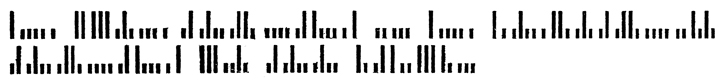
printing telegraph alphabets
primitives
US Patent No 309,600
UK Patent No 7,678 (1900)
US Patent No 1,021,189 (1912)
US Patent Nos 1,018,115 and 1,126,641 (1912, 1915)
US Patent No 1,053,042 (1913)
US Patent No 1,145,460 (1915)
|
US Patent No 1,077,278 (1913)
UK Patent No 29,057 (1914)
US Patent Nos 920,833, 963,213 and 982,659 (1909-11)
Morse Type (1916)
Morse Code Alphabet (nd)
US Patent No 1,547,492 (1925)
UK Patent No 7091 (1910)
Francis Galton (coding, and the "just-perceptible difference")
|
Circa 1909-1915, patents were granted for printing telegraph devices that sought to increase printing speed by minimizing mechanical movements. This was done by using a small number of fixed (or slightly) moving elements; whereby, for example, two, four, or six elements could be used to print all of the characters of an alphabet, plus numbers. Some of these were for purely mechanical printing (striking onto paper); others involved chemically treated paper and electrical charges. Remarkably, these systems utilized Morse and Baudot-like signals not only to signify letters and numbers, but to actuate the elements needed to assemble the printing characters themselves. In this way, they represent primitive instruction sets for letterforms. These particular codes were not devised for resilience against attenuation and the other insults that long lines might provide. Their primary objectives of were (1) to obtain high speed of operation, and (2) to do so with reduced wear and tear on terminal (printing) equipment, and thus reduced maintenance costs. And these alphabets were shortlived, if ever they saw the light of commercial day. It is my sense that the gradual perfection of multiplex printing telegraphy — the “New Telegraphy” engineered by Donald Murray and others — obviated the need for the approaches discussed below. The Murray High-Speed Automatic handled 1,200 letters (200 words) per minute. The new printers were fast, didn't rattle themselves to pieces, and could (along with repeaters and tape perforators) be used serially to handle several simultaneous feeds of multiplexed intelligence. There is a term — mosaic telegraphy — that roughly covers the assembly of the Dean, Kinsley, Ashley and Hulfish alphabets. “Mosaic telegraphy : Method of telegraph operation in which the patterns forming the characters are made up from units transmitted as individual signal elements.” (James F. Holmes. Data Transmission and Data Processing Dictionary. New York, 1965.) This would seem to rule out the dot matrix printer, which has is own rules for assembling letters that are separate from the transmitted ascii signals. I find the term “mosaic” in a contemporary (1961/62) description of a later printer, the Creed Model 1000 Output Printer. This machine is described as “using novel hydraulic principles with ‘mosaic’ printing by means of a 5 x 5 stylus matrix.” It shared with the earlier telegraphic alphabets and their mechanisms one purpose — speed; it was capable of 100 characters per second (1,000 words per minute). As noted below, some of the alphabets — notably Kinsley and Ashley — share features with seven-segment LED numeric displays. The most remarkable feature of such alphabets is their conflation of letter-construction and alpha-numeric symbol in a single level of code. This would be equivalent to employing ASCII or Unicode to actually assemble the letter, figure or glyph they identify.
|
Reusser's telegraph alphabet (1794) |
 |
 |
|
Reusser's alphabet
|
detail, A B G and H The original (1794) discussion provides no visual example; if it had, it would have shown an alphabet suited to German orthography, not English as shown here. |
Reusser's system is briefly described in Magazin für das Neueste aus der Physik und Naturgeschichte (1794): 183-184, and reappears in Highton 1852, Fahie 1884, and later A. H. Roberts, "The Romance and History of the Electric Telegraph, Part 2." The Post Office Electrical Engineer's Journal 16:3 (October 1923): 207-224. Roberts characterizes the system thus: The plan, as described by M. Reusser, was that each signal should be formed by broken spaces cut out of parallel strips of tinfoil which were to be attached to a pane of glass. Separate wires insulated and laid in glass tubes were to be provided for transmitting the signals. On completing the circuit by means of a battery of Leyden jars, or an electric machine, the breaks in the tinfoil strips would be illuminated by sparks passing across the small air gaps. (Roberts 1923: 211-12) Highton, mistaking Reusser for Reizen, writes: The first notice we find of Reizen's telegraph is inserted in the 'Magazine de Voight,' in 1794. His plan was as follows: As many wires were to be insulated and laid in glass tubes to a distant station as there were letters of the alphabet or different signals to be designated; each wire was to communicate with strips of metal placed upon a square of glass, the strips of metal were to be formed in the shape of letters, and instead of continuous metal, several breaks were to intervene, so that in the passage of electricity a bright flash would be seen at every break. Thus, when these breaks in a letter were many, and a current was passed through, the letter appeared illuminated from one end to the other. A wire of the telegraph being put into metallic communication with the commencement of each letter or symbol, when a discharge was sent from the electrical machine or from a Leyden jar over that wire, the breaks forming the letter became illuminated, and hence the letter was made visible. In this way letter after letter might be exhibited, and hence a correspondence carried on thereby. ¶ The preceding sketch, showing the tinfoil with the breaks therein, will explain Reizen's mode of communicating intelligence by means of electricity. (Highton 1853: 42-43) One might wonder whether the roman alphabet, diced and quartered in this way, would be legible in the form of "sparks." Moreover, why would a spark not deflect to a terminus one or two rows below or above? |
Gauss and Weber's alphabet (1833-38) Fahie 1884: 324, Sabine 1869: 33-38 |
Professor Karl August Steinheil's alphabet (1836-38) |
|
|
|
Fig. 24 ex Shaffner, Taliaferro Preston (1818-1881). The telegraph manual: a complete history and description of the semaphoric, electric and magnetic telegraphs of Europe, Asia, Africa, and America, ancient and modern (1859) |
|
|
Steinheil's alphabet was only one facet of his system, and less important indeed than his discovery that the "return wire" of a telegraph circuit could be dispensed with, and the earth itself be employed for that purpose. We attend here only to the "elementary signs" from which Steinheil's alphabet is composed. Shaffner writes : ...and turned toward the indicator, one immediately perceives the beck imprint a dot upon the ribbon paper as it moves along. The intervals of time between the successive repetitions of this sign, are represented by the respective distances between the dots that follow in a line upon the paper. On turning the fly-bar from left to right toward the operator, the deep-toned bells ring, and the second ink cup marks down a dot upon the paper as before, not, however, upon the same line with the former dots, but upon a lower one. High tones are therefore represented by the upper dots, and the low tones by the dots on the lower line, as in writing music. As long as the intervals between the separate signs remain equal, they are to be taken together as a connected group, whether they be pauses between the tones, or intervals between the dots marked down. A longer pause separates these groups distinctly from each other. We are thus enabled by appropriately selected groups thus combined, to form systems representing the letters of the alphabet or stenographic characters, and thereby to repeat and render permanent at all parts of the chain, where an apparatus like that above described is inserted, any information that we transmit. The alphabet which is chosen represents the letters that occur the oftenest in German by the simplest signs. By the similarity of shape between these signs and that of the Roman letters, they become impressed-upon the memory without difficulty. The distribution of the letters and numbers into groups consisting of not more than four dots, is shown in the alphabet, figs. 23 and 24. In order to explain more definitely figs. 12 and 13, the following figs. 21 and 22, with their sectionals more particularly described, are inserted. (pp175-5) |
The system operated with a single line and positive and negative currents, respectively actuating two needles carrying small cups of ink. These reservoirs have very fine perforated becks which, by capillary action, bring ink down to "form at their apertures a projection of a semi-globular shape." (Shaffner : 176). Deflecting magnets brought either a "positive" or "negative" needle (and its respective ink device) into contact with the paper, in either a left or right hand line. This action is shown in the drawing at right (Shaffner's Fig. 23). Steinheil is said to have developed an acoustic version of the system in which the positive and negative currents caused to be struck bells of different notes (high for positive, low for negative). It is thus similar to the Morse sounder.
|
|
|
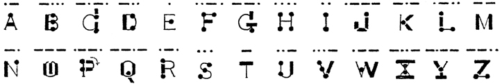
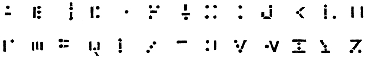
The emphasized passage about similarity to Roman letters overstates that similarity. First, one needs to draw the lines to connect the dots of the letters. While some of the resulting figures resemble skeletal forms of their respective letters — A, F, L, M perhaps, S, V, Z — most do not. At best, the resemblances would be suited to a mnemonic device for operators learning the Steinheil alphabet. Its inclusion here, among elementary signs for printing telegraph alphabets — is perhaps a stretch. Still, even the attempt to use a binary code and a series of dots to describe alphanumeric characters looks forward to, for example, the Dean alphabets of 1909-11. The mnemonic aspect of the Steinheil alphabet is echoed in at least one "Morse Code Alphabet" I have encountered, in which the Morse dots and dashes are incorporated in skeletal representations of the capital letters A-Z. Training of Morse operators was always by ear, not eye, however. (Conversely, one can still find teletype veterans who can read five-unit perforated tape as if it were printed in alphanumeric characters.)
|
US Patent No 309,600
|
Autographic Reed Telegraph |
Byron A Brooks (Brooklyn) |
|
|
|
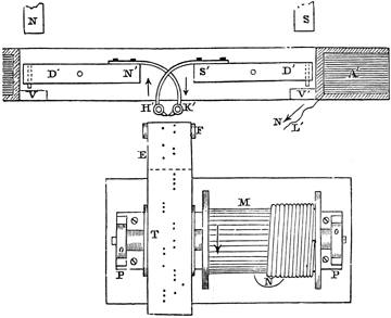
“...the novel application of the 'harmonic' system to rapid and autographic telegraphy, by means of which I am enabled, without the intervention of printing mechanism, to transmit and receive a message in ordinary Roman or other characters over a single-line wire.” (1:15ff) |
“When a letter passes under the fingers s s', &c., the contact between the said fingers and their contact-points will be intermittently broken. As these contacts are severally broken the circuits through the corresponding fingers at the receiving end of the line will be closed through the sensitized paper, and a discoloration or mark will be produced thereon corresponding in length to the length of time the said contact at the sending terminus remains disrupted. ¶ In this way it is possible to arrange a sufficient number of fingers so that a complete letter or character will be reproduced at the receiving end of the line over one wire, and with great rapidity.” (2:79ff) |
|
At sending station, letters are printed in insulating ink on prepared paper; as the tape passes under five styluses, circuits are broken as a stylus rides over its respective part of a letter. At the receiving station, the device prints letters by five (harmonically controlled) pens, against which paper strip is drawn. The patent does not so much specify the alphabet itself, as the five pens that would draw the horizontal markings that constituted each letter. The marks made need not be letters or numbers; no attention is given to the form of the marks, to optimize their five-row construction. The same patent cites Brooks's type-writing machine (with piano-like keyboard) described in 1883 US 274,262. Brooks is also known for the Travis typewriter, which was manufactured in the 1890s.
|
|
GB Patent No 7678
|
An Improved Automatic Letter-writing Telegraph |
Anton Pollak, Josef Virag, Julius Egger and Dr. Friedrich Silbertstein (Hungary and Austria) |
|
|
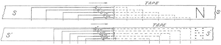
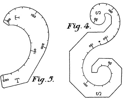
"This invention has for its object an arrangement for forwarding telegraphic news in the form of ordinary writing (written characters) which differs essentially from the so-called type printing telegraphs hitherto known in that the current impulses corresponding to the signs or characters to be written down, which are sent into the line wire by means of an automatic dispatching device, influence the recording mechanism of the receiver in such a way that it records the separate characters in a continuous line... |
Fig. 4 [lower section in exhibit above] shows the perforations necessary for drawing the first six letters of the Gothic alphabet shown in Fig. 3 [at top]. |
Claims that on average, a letter won't require more than three perforations; certain complicated characters would of course require division in a greater number of elements, "and the length and mutual proportion of the perforations must be selected to suit the character of the elements to be recorded." (6:28ff) (One can envision, however, a special stenographic alphabet — needing to be learned, of course — that would dispense with loops.) Claims also that it "serves for a very rapid transmission of telegraphic messages," but speed does not appear to be the primary objective of this specification. This specification might be passed over as relating to siphon recorder tracings, but its marks are more complex, and indicate more than the reverse polarities of Cable Morse. The patent does not, however, number the total elements. It might qualify as a form of stenography — or econo-graphy, in the sense of economy of parts.
|
US Patent No 1,021,189
|
Alphabetical Symbols |
Irving Hill (Wallace, Calaveras County, California) |

|
This specification "relates to improvements in alphabetical symbols for code cipher purposes," but does not mention telegraphic application. The system assembles its symbols from a "common base," and it is the idea of a common base of elementary signs that interests us here. Each of the vowels A E I O U is given several forms, respectively indicating a phonic feature.
|
US Patent No 1,126,641
US Patent No 1,018,115
|
Telegraphic System and Apparatus Carl Kinsley (Chicago, Illinois), assignor to Globe Printing Telegraph Company (Michigan) |
|
|
|
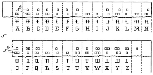
the full 1915 alphabet. |
detail of printing assembly, highlighting elemental types. |
Kinsley's system combines features of "the two old methods" — mechanical printing telegraphs and chemical recorders, by substituting electrical action for the printing. Either six or eight magnets can be used, thereby "permitting the use of eight instead of six elements for printing." The Figure shown above details the complete set of six receiving magnets, their "tips or attachments" shown "black and heavy" — "although in practice they are light and thin" — against part of their gray magnet assembly. The respective magnets are actuated in sequence, not at once; "The imprint of the three horizontal lines with the two short verticals produces the letter E. The tape P during operation of the apparatus is constantly fed along under the pens, and the speed of operation is so high that even if a group is worked in succession instead of simultaneously, the imprint will be quite legible." Regarding speed, Kinsley continues : "...since the letters or other complete characters are formed by combinations of the various elemental imprints, it follows that variation of the receiving tape speed without varying the rate at which the impulses are being sent will merely widen or make narrower the received characters... Variations in tape speed, therefore, while they do alter somewhat the general appearance of the received characters, do not alter their legibility unless they are extreme." In developing my purpose, and in seeking to improve the existing methods, I have found it expedient to combine features of the two old methods — printing telegraphs (and) the chemical recorders employing a code — in such a manner as mutually to neutralize their defects and to mutually reinforce their advantages. It may be true that no system wherein masses have to be moved bodily will ever attain theoretical freedom from speed limitation, or even attain the ultimate speed at which recording tape can be driven, but as this speed is very high its attainment is not necessary. In any equation for the speed of receiving, the line constants and the instrument constants are the factors principally affecting the result, and, disregarding the line constants, by reducing the inertia in the instruments we can gradually raise the resultant speed until the theoretical limit is approached... I have found it possible to continue the reduction beyond any limits heretofore reached. To do this I have discarded mechanical printing mechanism, whether of the impact type or others, and while I directly record legible characters, I substitute electrical action for the printing, thus borrowing one feature from the chemical methods. As the impression does not depend on the possession of mass, or the momentum of the printing member, I am enabled to employ greatly attenuated masses, approaching the theoretical limit to which I have referred. (2:24ff) The system requires pre-punching of tape prior to transmission. A six-unit tape identifies the letter, but also provides the code by which their respective elementary signs are actuated to form individual letters. The code therefore is an instruction set for the assembly of each letter. |
US Patent No 1,053,042
|
High-speed Telegraph System |
Carl Kinsley (Chicago, Illinois) |
|
|
|
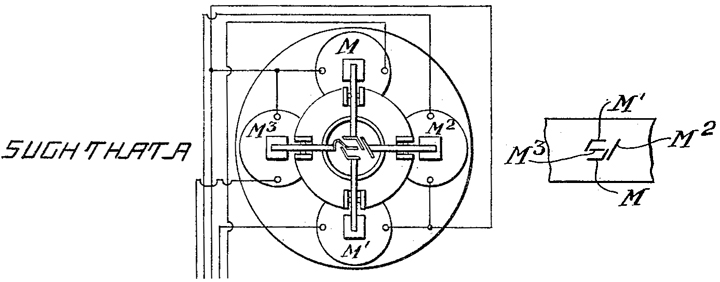
At right are shown the "impressions produced by the four printing elements controlled by the four magnets M, M1, M2 and M3 respectively." |
An improvement on the preceding Kinsley patents: four printing elements. Requires "only a single line wire," using opposite polarities plus current of two strengths. "Two of the relays respond to positive currents, and two to negative currents; and I differentiate between the relays and their associated printing magnets of each pair, by winding the relays to respond to different current strengths." (1:61ff) Kinsley conceives that printing might be in the form of "chemical printing disclosed in my prior applications before referred to, or printing by impact using a typewriter ribbon, cabon paper or the like." (3:77ff) The alphabet is not included among the claims of the present invention, and is therefore not illustrated in full. (3:90ff) The magnets and their respective printing elements are actuated by perforated tape, specifically by four feeling springs each one dedicated to holes in one channel.
|
US Patent No 1,145,460
|
Printing-Telegraph System and Alphabet |
Charles G. Ashley, assignor to General Engineering and Construction Company (Toronto) |
|
|
|
seven printing pens |
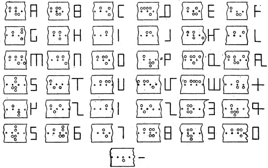
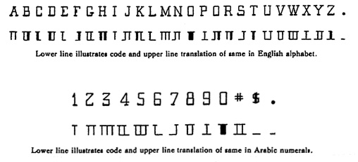
The Ashley alphabet differs from the General Engineering alphabet in the number and arrangement of elemental types, and consequently in the appearance of the characters themselves. The system, that appears to predate UK/1912/29,057, employs seven printing pens. The Ashley system replaces Morse (or any similar elemental code), to transmit "in a predetermined sequence, current impulses of variant intensities and variant polarities, to cause the selective operation of type faces to record on a receiving surface characters of the Roman alphabet that are directly readable by the uninitiated layman, placing no requirement upon the receiving operator, but that he shall be able to read a language printed in Roman characters." (1:29ff) The same specification later points to another virtue, that "every letter or numeral is printed without any useless appendage, thus greatly increasing the clearness of the recorded message." (5:32ff) By "useless appendage" here is meant overlapping or other linkage with adjoining forms; the aim of course is simplification. |
|
|
In this as with the earlier General Engineering patent, the "number of impulses for a given message will be small as compared with the number of pen operations required resulting in a slower commutation of currents in the line for a given speed of transmission as measured in number of words per unit of time." (5:42ff) |
US Patent No 1,077,278
|
Printing Telegraph System and Alphabet |
David S Hulfish, William J Herdman and Egbert S Lorimer (Toronto; assignors to General Engineering and Construction) |
|
|
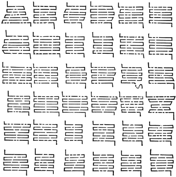
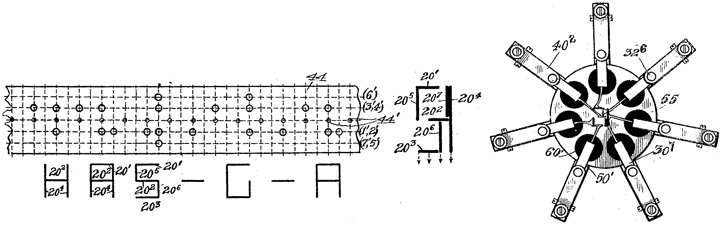
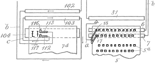
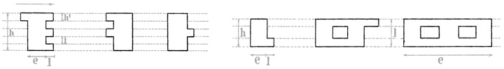
The exhibit shown above is adapted from Figures 2 (to which is added color to aid comprehension) and 5, the latter showing a "sectional transmitting tape perforated to send all of the characters necessary to transmit intelligence in the Roman alphabet." (2:111ff) Letters made up of combinations of six elementary types : (1) upper horizontal; (2) lower horizontal; (3) upper diagonal SW-to-NE; (4) middle horizontal; (5) upper vertical; and (6) lower vertical. |
"Thus a perforation along the line - 1, in the transmitting tape, will cause the imprinting of type element 1'..." The full arrangement — incorporating four electromagnets and impulses of positive and negative polarites — is outlined here:
|
The width of a complete normal character is divided into four arbitrary units, while the types are separated from each other longitudinally by one of these units. (2:106ff) Exceptions include "D", which is a "double spaced letter or twice the width of a normal character." (3:84ff) The alphabet derived from six type elements is quite a bit easier to read than two other General Engineering specifications — Ashley's six-element alphabet shown immediately above, and the four-element alphabet shown below. It may be, however, that the working of the tape advance mechanism to allow successive imprints of the type elements required for each letter, was prohibitively complex.
|
UK Patent No 29,057
|
Improvements in and relating to Printing Telegraphs |
The General Engineering and Construction Company (Toronto, Canada) |
|
|
General alphabet (1912/14) |
elementary types |
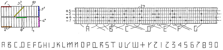
Letters made up of combinations of four elementary types : (1) upper horizontal and vertical lines; (2) middle horizontal line; (3) lower horizontal and vertical lines; (4) upper & lower vertical lines; "letters and numerals are resolved into a certain small number of elemental lines all of which are recorded by type and transmitted by electric currents fewer in number than the number of elemental lines." There appear to be two elemental lines, above and below the larger holes in the middle row of the grid, which latter are for the wheel drive mechanism. In addition to the four elementary types, the system may superimpose a part of one type on that of another. It has something in common with seven-segment LED numeric displays, but employs ingenious combinations of sub-elements to yield a readable alphabet as well, albeit an eccentric one — note the tail of the "D" (result of elementary type 3), and the northeast part of letter "K" (elementary type 1).
|
US Patent No 920,833
US Patent No 963,213
US Patent No 982,659
|
Robert L. Dean |
|
|
|
"Code of the Dean Rapid Telegraph Company" |
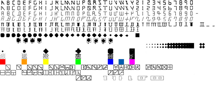
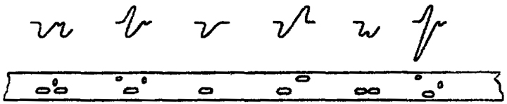
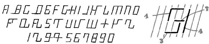
I first encountered the "Code of the Dean Rapid Telegraph Company" in the form of an advertising card. It could be read with effort and looked vaguely machine-readable, but I could make no further sense of it until several years later, when Dean surfaced in a methodical look through the patent literature. The image below shows three categories of marks: The Dean "code" alphabet (middle rows), the ordinary alphabet (below) and atop both, "character holes" (Braille-like embossments in a later patent) that by their contact with a contact device complete circuits that actuate the printing characters for each respective letter. |
|
|
|
Figure 12 from Patent No. 920,833 |
Each letter of the Dean alphabet is assembled from a unique combination of one of several of five basic components: Right and left vertical strokes, right and left bold vertical strokes, and a lower crossbar. "A" is formed by a left and right vertical; "B" by a left vertical and a right bold vertical; "C" by a bold left vertical alone. The letter "H" is formed from left and right bold verticals. And the letter "L" employs a left vertical and the lower crossbar. The figures 0-9, as shown in the 1910 "Code of the Dean Rapid Telegraph Company," seem to involve additional elementary signs: a short horizontal crossbar (for the "period"); and a filled counter (letter "O" and numeral "0"). The short crossbar might be an elementary unit of the longer crossbar, as is suggested by the form of the numeral "9." We turn next to the instruction set. There are two registers of "contact holes," an upper and a lower register. These contact holes are of two widths: one and two units wide. The upper register actuates the printing mechanism for the crossbar; the lower register actuates the printing character for the vertical. Two lower-register holes in quick succession will actuate two verticals, yielding (as we have seen), the letter "A." |
|
|
|
detail of contact and printing assemblies, Patent no. 920,833 |
|
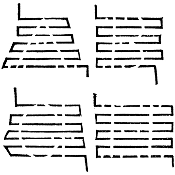
Patent No. 920,833 explains: "when printing the letter A two short impulses with but a slight intervening pause will be transmitted through the contact roller 17 to character 117." (Contact roller 17 can be seen at right, above; its corresponding character 117 can be seen at left.) The letter "D" is formed from a bold left vertical, right vertical, and lower crossbar. Dean explains its instruction set as follows: "When printing the letter D one long and one short impuse will transmitted through roller 17 to character 117 and one short impulse will be transmitted through roller 18 to character 116 during the pause between the long and short impulse just referred to. By first transmitting a long impulse to character 117, the first vertical element of D will be wider than the second and thus render D easily distinguishable from B in which the reverse condition exists." The movements of the sending and receiving mechanisms are synchronized. The patent does not dwell on the means of the synchronization. More important for our present purposes, however, some explanation is warranted of the arrangement of contact holes in the upper and lower registers. It will be seen that "the character-holes of one row [are] arranged with respect to those in the companion row... so that one roller of the contact device... will not enter a perforation in one row until its companion roller leaves a perforation in the other row. Thus short circuiting, which would prevent the transmission of proper impulses to the receiver, will be obviated." The whole unit is a page printer, in which a worm drive enables "reading" and printing, line by line, in a reciprocating action. The original is a page prepared with control holes, whose locations in rows on the page match the locations of their respective letters whose printing they actuate. The system has something of the character of a stencil, whose copying takes place over a distance; it differs from what would come to be known as a "page printer," actuated by the Murray five-unit code and incorporating "stunt" symbols for "carriage return," upper and lower case, etc. All of these patents date from the years that the Murray and similar systems were being perfected. I imagine that their improved engineering and ruggedness also recommended them over the Dean and similar systems. "Thus," the Specification for 920,833 concludes, "it will be understood that by employing this alphabet and printing the letters thereof in the manner described, all complicated mechanism, such, for instance, as sunflower apparatus may be dispensed with, and at the same time I obtain separated letters which, owing to their similarity to those of the English language, may be read at sight with but little practice." (5:21ff) US 982,569 provides a little more clarity about the relationship of the (code) embossments and the Dean alphabet, and especially for embossments whose spacing is unequal — Those "studs of different diameters and spaced unequal distances apart" are what distinguish the Dean alphabet from the tactile braille alphabet that it resembles, at least for its minimalism. At closer inspection, it is not so minimal but rather a visual alphabet whose letters are differentiated by slight variations of spacing, thickness, and deployment of horizontal elements. A fourth patent is assigned to the Dean Rapid Telegraph Co., but is not associated with Dean himself, but with its inventor George Wood (Kansas City, Missouri). US patent no 1,064,805
The Wood patent focuses more on the receiver mechanisms, transmission of impulses, stylus carriage action, and so forth; nowhere does it describe the stylus — still less the alphabet used in the system — in greater detail than this : "The stylus embraces two character-bearing levers controlled by two electromagnets energized by a local printing circuit controlled by a polarized relay..." (1:23ff)
|
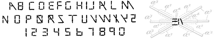
Described below are a few telegraphs-related letterforms that do not fit under the heading "elementary signs," but that need to be captured here. The Legros/Grant Morse alphabet, and the mnemonic Sambrook Morse Code Alphabet, have little in common with each other except to make Morse "readable;" they share even less with the other alphabets examined on this page. Grant's 1920 patent for the production of formers for punch cutting machines is an early "piecewise polynomial spline," while Francis Galton's system for describing and coding a line drawing is a kind of "chain signal code," similar in some ways to the operation of a certain kind of chess code.
|
Legros and Grant, Morse Type (1916) |
 |
|
|
translation : THE MORSE ALPHABET IS THE TELEGRAPHIC ALPHABET OF ALL NATIONS |
|
|
Fig. 85, Morse Type; Estienne Form
|
"In this form the printed message has the advantage that the same actual length of line is occupied by the symbol sent, whether dot or dash, but like the 'sounder' it has not the advantage, possessed by the tape, of similarity to the actual impression to be made on the brain of the receiving operator. The visible interrupted line of the tape resembles the wireless telegram as heard in the telephone receiver and is as easy to read ; it is this perfect clearness of the telephonically-received wireless message that has led the authors to devise a similar system of embossed type for the blind to which allusion is made later."
|
|
I see no practical use for Morse Type shown above, but note in passing its superficial similarity to the Dean code. Note also the single marking space separating letters, and the double marking space separating words. Braille and other reading devices for the blind form a small subset of patents relating to printing telegraphy.
|
|
Morse Code Alphabet (nd) |
 |
|
|
Morse Code Alphabet. Arranged by A. Norman, Sambrook School of Memory, Lincoln, England.
|
(nd, detail; BL 1804.b.31) |
|
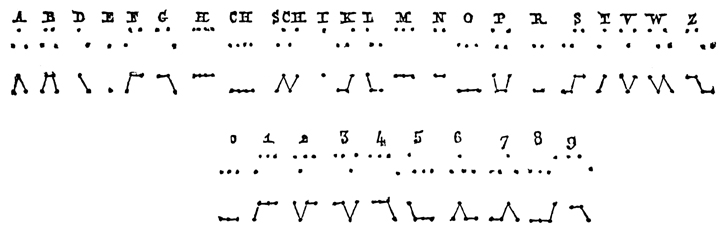
Here, the alphabet functions as a mnemonic device for Morse. The displacements of dashes and dots are somewhat arbitrary, from letter to letter. The alphabet is not so different from the Legros/Grant Morse alphabet described immediately above, although arguably more economical of character width. The Norman alphabet also shares some formal features with Professor Karl August Steinheil's alphabet (1836-38) described among the primitives above — notably, the need to "fill in" the missing strokes to describe the full letter. The comparison is flawed, in that the Norman alphabet, at least, was not intended for use in its naked, dot-dash construction form. But we can still examine it against its own grain, in asking whether each letter makes evident the sequence of dot and dash it represents (here, the letter represents Morse, rather than the other way around). Some do, some don't. The mnemonic is purely pragmatic. Alphabet, mnemonic device, symbol — the evidence can be hard to classify. |
|
 |
|
|
same, minus strokes. |
|
US Patent No 1,547,492
|
Special Alphabet for Messages Sent by the Telephotographic Process |
Eduoard Belin (Paris) |
|
The Belin alphabet, features of which are shown above, does not easily fit among the elemental signs : letters described on this page. It is specifically designed for use in copying telegraph systems and, of those, for those employing relief plates wrapped round a drum for exploration by a stylus. However, because it is an alphabet, I include it here. This specification concerns the optimal design of characters for "exploration" by means of a "pointed member" (stylus) or like device; such characters might be in relief or in some form of nonconductive ink. The object here is to ensure maximum efficiency of form, dimension and spacing of character, to ensure that no essential feature is missed in the scanning process. "The character of the alphabet should not contain elements the width of which is so small that they cannot be explored by the point when this point describes two consecutive spirals." (1:44ff) It is probable that the surface would be prepared for cylinder or drum scanning. The Drawing shows only notional characters in two figures: The characters in Figure 1 are best suited where the exploration spirals are close together; the characters in Figure 2 are better suited for operation at high speed — they provide increased redundancy of form and feature. The characters are conceived as being "used for typewriting purposes," and thus presumably need to be readable to the initiated, perhaps in the way five-unit code on perforated tape could (and can!) be read. In standard patent conditionality, it is claimed that the characters "may represent letters, combinations of letters, dipthongs or even words."
|
UK Patent No 7091
|
Improvements in and relating to the Production of Formers for Punch Cutting Machines. |
John Cameron Grant (engineer, London) and Lucien Alphonse Legros (engineer, Watford, Hertford) |
|
A different description of the same device :
|
|
This specification is not telegraphic. I include it here for two reasons. The instruction set implicit in its use of "logarithmic spirals" and an x-y coordinate grid could be transmitted by telegraphy. And it is an opportunity to draw attention to L A Legros and J C Grant their Typographic Printing-Surfaces (1916) which covers, if only in its appendixes, some of the patent specifications described here. Most of the specification is devoted to pantograph framework, formers, the preparation of a mould in wax or other material, etc. Yet in the detail presented here is the idea of vector art — a sequence of equations defining an irregular curve. And herein, in nuce, may lie the essence of telegraphic expression : a shorthand means of transmitting a complex message across either time or distance, in abbreviated, unambiguous and rugged form. If written out as an instruction set, the Grant-Legros curve would be a kind of Piecewise Polynomial (splines). Richard Southall refers to piecewise quadratics in his discussion of Donald Knuth's metafont (Printer's type in the twentieth century : manufacturing and design methods. 2005 : 188). Several Grant patents had to do with fluids — e.g., GB_1919_130156 "Improvements in the Raising of Water by Means of Endless Tubes Revolving round Pulleys and Discharging their Liquid Burden and Contents by Centrifugal Action" and 1919 GB 128721 "Improvements in and relating to the Raising of Water and other Liquids of Low Viscosity" (not to mention his 1897 GB 189612130 "Appliance for Preventing Cats and other Animals from Climbing Over or Passing Along Walls and the like").
|
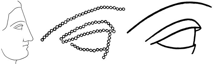
Francis Galton (coding, and the "just-perceptible difference") Francis Galton (1822-1911) his “The Just-Perceptible Difference” Proceedings of the Royal Institution 14 (January 27, 1893) : 13-26 provides other means for describing an outline shape. His purpose here, and in several other publications devoted to descriptions of profiles, fingerprints, etc., related to research and statistical compilation of data for his research in and theories on eugenics. See for example Galton, Francis. 1910. “Numeralised profiles for classification and recognition.” Nature 83 (1910) : 127-30. We do not pursue this here, except to note polymaths like Galton and his contemporary Charles Sanders Peirce were both interested in the development of telegraphic codes. His example is the profile of a Greek Girl, shown below. Galton prescribes not the eight orientations of a chain code (see below), but a code involving the 16 principal points of the compass : N NNE NE, etc., to each one of which is assigned a separate letter, e.g., a> for North (top of paper), b for NNE, c for NE, and so on in order up to p. "This makes e represent east, i south, and m west. Each point (indicated by circle) on the eye profile is the starting point for the direction to the next point on a grid — say 50 dots to the inch. In addition to the orientation letters a through p, he employs r and s to indicate brackets — that is, the start and end of an unconnected curve or line — and letters u v and t as "points of reference." Galton's full description of the eye reads : URkkk kklll mSVap ponmn mmlmm mlmlm llmZZ VnTnn mnmmm mmmlm mmnZZ Tjjjj jjkke chmmn mnun [sic] ononZ . I take Galton on his word that this cipher sequence does indeed describe the eye. Seventy-nine letters are used to describe this rather complex shape; Galton is able to capture the entire profile of a Greek girl in 342 small circles, described by a cipher of 271 letters. |
|
|
This image, whose "mislaid original has now been found," is an "extra plate" in Karl Pearson, The Life, Letters and Labours of Francis Galton Vol IIIA (Cambridge UP, 1930) |
"The reader should place this plate some ten feet from his eye, and gradually approach it, noting the distance at which the 342 small circles become distinguishable." |
At first sight it may seem to be a silly waste of time and trouble to translate a drawing into a formula, and then, working backwards, to retranslate the formula into a reproduction of the original drawing, but further reflection shows that the process may be of much practical utility. Let us bear two facts in mind, the one is that a very large quantity of telegraphic information is daily published in the papers, anticipating the post by many days or weeks. The other is that pictorial illustrations of current events, of a rude kind, but acceptable to the reader, appear from time to time in the daily papers. We may be sure that the quantity of telegraphic intelligence will steadily increase, and that the art of newspaper illustration will improve and be more resorted to. Important local events frequently occur in faroff regions, of which no description can give an exact idea without the help of pictorial illustration ; some catastrophe, or site of a battle, or an exploration, or it may be some design or even some portrait. There is therefore reason to expect a demand for such drawings as these by telegraph, if their expense does not render it impracticable to have them. Let us then go into details of expense, on the basis of the present tariff from America to this country, of one shilling per word, 5 figures counting as one word, cypher letters not being sent at a corresponding rate... (Galton 1893: 24, online via galton.org) Galton's device is akin to a chain signal code, that is, a "pixel-by-pixel direction code that defines boundaries of objects within an image. The chain code records an object boundary as a series of direction codes." Those directions are eight in total, moving counterclockwise around the perimeter of a 3x3 unit grid, starting at NW (1) and ending at east (0). It might be noted here that Galton's first published work was The Telotype: a Printing Electric Telegraph (London, 1849; a later version was published by John Weale in June 1850). Galton's projected machine was a printing needle device (three needles, 3 x 3 x 3 = 27 signals, doubled by a "switch" signal. The deflecting needles would complete local circuits to actuate the printing mechanism, which was far better than to require on the signal current itself to actuate the printing mechanism. For a description and a PDF of the full 1850 publication, see galton.org > collected works > by year > 1850. (Galton.org is a remarkable and useful labor of love.) It is here that the discussion of elementary signs for letters leaves off to enter the picture discussion. None of the codes for letterform instruction sets described above are equal to five-unit Baudot/Murray code for describing alphabetical intelligence, in which each letter is described by the same number (five) of elements. These codes are, in essence, not translations for the symbols "a" or "b", but rather instructions for drawing a certain kind of picture — an image, that is, of an alphabetical letter. The two different ends : letter (unconcerned with the actual making of that letter), and picture (of letter), can be seen today in ascii or Unicode on the one hand, and postscript description of letters on the other. It is remarkable that letterform description code can be found so early. I doubt that the Dean, Kinsley, General Engineering or other perforated tape codes described above were an efficient way to "pack" alphanumeric intelligence, acknowledging however that that was not their purpose.
|
|