telegraphic codes and message practice |
|||
|
|
programmable advertising signs UK Patent No 17,806 (1897)
US Patent No 862,3436 (1907)
|
US Patent No 1,172,455 (1916)
US Patent No 1,504,112 (1924)
|
|
Electric signs are not telegraphic, but they can be programmable, and their use of elemental units does relate to the "elementary sign" printing "types" described elsewhere in this section. Hence, I include four specifications for electric signs designed to display a succession of letters and other forms using the same set of elemental shapes; in some cases, their mechanisms are controlled by perforated tape. The Current US Classification for these patents is 40/452 (40 : Card Picture or Sign Exhibiting. 452 : Changing exhibitor, illuminated). A close examination of Class 40 might well yield additional specifications involving elementary signs for letters. The European classification -- at least for Hildburgh -- is G09F11/34 Many of the patents in this category emphasize the letterforms themselves, rather than the "programmable" switching mechanisms. Certainly, the purpose of these devices is quite different than the Dean and other "high speed printing telegraph" systems. Moreover, these printing telegraph systems offered only the most primitive letterforms. In contrast, many of the sign patents give more attention to letterform design features for what are, after all, "display" faces. At least four general types of "changeable" or "talking" signs (to borrow an expression from Lenora H Jones US/1914/1,114,267) are encountered in the patent literature:
|
|
UK Patent No 17,806
|
Improvements in Advertising or Signalling |
Charles Raleigh (milling engineer, Surrey) |
|
|
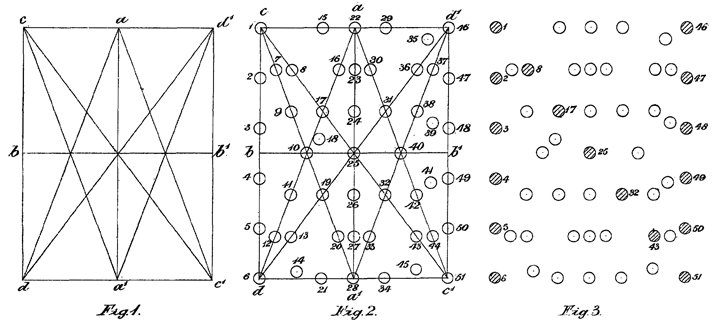
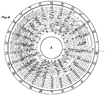
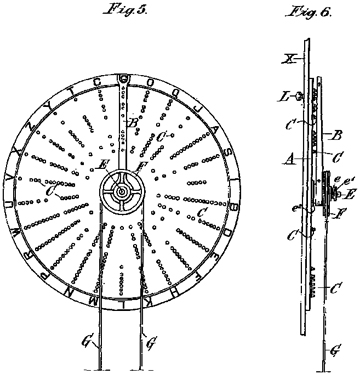
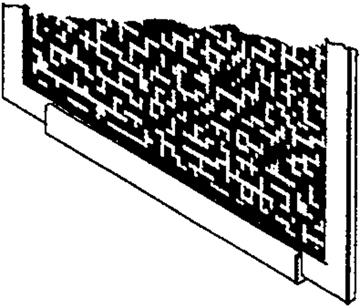
"Signals, electric- lamp. -- In advertising or signalling with the aid of letters or other signs delineated by means of electric lamps &c. the lamps are arranged in such a manner that the greatest number of letters or signs may be formed in the space occupied by one letter with a minimum number of lamps. Fig. 2 shows the manner in which fifty-one lamps may be arranged for producing at will any one of the letters of the alphabet, the greater number of the lamps being arranged symmetrically with regard to the horizontal or vertical axis of the figure. The lamps corresponding to any particular letter are illuminated by the use of a switchboard, Fig. 5, marked with the letters of the alphabet, and having a radial arm B which, when moved into the position corresponding to the letter desired, engages with a series of contacts arranged radially on the board and corresponding to the lamps required to form the letter." (from abstract) |
Note that the lamps are not arranged in perfect symmetry. "The present invention is designed with the object of producing the maximum number of letters or signs with a minimum number of illuminating or equivalent devices, an appreciable saving of space being effected." (1:8ff) "By these means, the whole word is reproduced within the space of one letter. Similarly, the whole alphabet with the numerals the the L, s, d signs may be produced with the assistance of sixty-nine lamps. By employing a number of such groups, words or other combinations may be produced." (1:25ff) |
|
|
|
above :
Shown at left is the elevation and profile of the contact disk, together with the rotating contact-arm B. The contact disk contains the "program" for every letter, and might even be arranged "to suit the order of letters required" where 'set" advertisements were to be reproduced. The disk is akin to perforated tape, which is incorporated in the Hildburgh system. |
|
Raleigh makes much of the economy of bulbs achieved by his "artistic" spacing. "The letters, moreover, instead of being of grotesque or unnatural formation retain their well known configuration -- rounded curves and straign lines -- the lamps constituting the same being equally and artistically spaced. No useless lamps in any letter are illuminated, and with the aid of the improved designs constructed according to my methods, the maximum amoung of definition is obtained with a minimum number of lamps."
|
|
US Patent No 862,343
|
Flash Sign |
John S Nesbitt (Victoria, B.C.) |
|
|
|
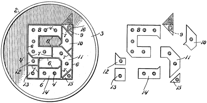
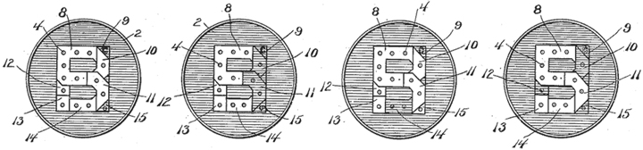
"The compound letter frame consists of an open trough shaped figure the walls 6 of which are secured to and project from the outer face of 3. The conformation of the figure 6 is of such general outline that it will inclose within its limits the several letters for which it is designed, in this case B E R and 5 c. This compound letter frame 6 is divided by partitions 7 into sections 8, 9, 10, 11, 12, 13, 14 and 15, which when illuminated in certain combinations by electric light bulbs in the sockets 4, will show forth the desired letter while the other sections not required for the formation of such letter will remain in darkness." (1:30ff) |
|
|
US Patent No 1,172,455
|
Advertising Machinery |
Walter Leo Hildburgh |
|
|
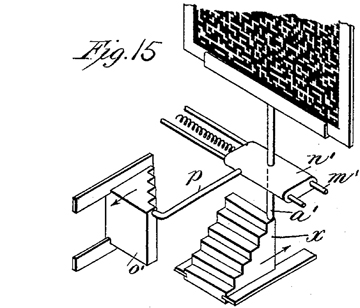
Figure 15 demonstrates the step mechanism that would cause the movable plate to move up or down six units on the y axis, and right or left through the 5 units on the x axis, for the respective holes in the array of "unit areas" to align against and show through the grid of holes in the stationary plate. |
Detail of patent Figure 15, being only example of what a "movable plate" would look like. It is a large grid, composed of multiple "unit areas," each 1/2 inch wide and .6 inches "deep," and each holding a maximum of 30 "holes." |
|
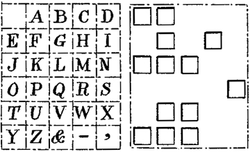
This patent "relates to improvements in devices for producing changes in designs or advertising or other purposes and is especially applicable to devices in which a plurality of relatively movable plates is employed. One of said plates is provided with visual openings equally spaced in parallel lines and the other plate is provided with visual areas so arranged that, by the relative movement of the plates, some of the areas of the second plate will be brought into coincidence with some of the openings in the first plate and produce a desired image." Hildburgh's improvements relate to control of the relative movement of the plates, using code on a perforated card. While his device is not limited to letters, his example is devoted to the 26 letters, three punctuation marks, and an empty square.
|
|
|
|
Figure 1a, at left above, "is a diagram showing the position of the blocks for presenting thirty independent designs whicn used in conjunction with a suitable opaque plate. Figure 1c [to its immediate right] is a view showing the visual areas in a unit area of the market plate." (1:47ff) |
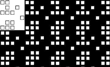
The image above takes the exampled unit area, and multiplies it as it might appear on an actual movable plate -- see the image from Figure 15 further above. An actual pattern would be more various than is shown here because of the different values (limited, here, to black and white) required by each letter at a given x-y coordinate. Hildburgh's GB/1908/22,073 provides a means by which something akin to anti-aliasing might be achieved: "By making the blocks in some portions of the designs of smaller size than those in others an effect of partial shading may be produced. The fields of the designs may be filled, instead of by unblocked open spaces, by blocks having large apertures of various shapes -- circular, diamond-shaped, heart-shaped, etc. -- in order to produce more striking effects." (3:35ff) The idea is similar to those provided by Ellero, Montagna and others, and summarized in the companion page for elementary signs : pictures. |
|
|
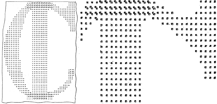
Figure 24, shown immediately above, is an elevation "of a portion of a movable plate." |
The detail of Fig. 24 shows the relationship of the holes for two letters on the movable plate; it should go without saying that the array of holes in the permanent plate essentially mask all but the holes for a single letter on the movable plate, thereby making it impossible for two letters to be seen in this way. |
"Several movable plates may be used simultaneously with one stationary plate. For example, a second movable plate giving any number of designs, may be fitted together with the 30-design ovable plate previously described, for the purpose of giving various colours to the designs as they appear; or a second movable plate capable of producing a new set of thirty designs may be used with the original plate, twenty-nine of its designs appearing when the original plate stands at vacancy (or at clarity, if vacancy is produced by the closing of all the open spaces, while twenty-nine of the original plates' designs appear when the second plate stands at vacancy (or clarity)." (8:57ff) Hildburgh also provides for the lenses to be deployed between the light source and the apertures, which "serve several purposes : first, to collect the light from a large area and cause it to pass through an aperture in the plate; and second, to cause the light to be distributed after it has passed through the aperture." (4:84ff) The general principles behind the Hildburgh patents appear very much later; this patent is cited by Eckert US/1981/4,246,713 (Illuminated advertising display device with changing visual effects) and Dehli US/1997/5,657,565 (Compact display apparatus). For our purposes -- elementary signs -- and notwithstanding the ingenuity of his mechanism itself, the significance of Hildburgh's ideas resides in the reduction of his alphabetical letters into pixel-like units of diameter 1 that can never be closer to each other than five diameters on the horizontal, and six diameters on the vertical (? !). Walter Leo Hildburgh (1876-1955) filed ten patents listed in espacenet, two of them for dynamo electric machinery the rest -- including two Austrian patents -- for advertising machinery. There are at least two other U.S. patents. Some archival material is at Columbia, where he trained as an electrical engineer (E.E., 1897; A.M., 1898; Ph.D., 1900). Hildburgh traveled extensively, lived in London and thanks to a modest independent income devoted his life not to engineering but to art collecting and scholarship (medieval Spanish enamels, amulets, alabasters, etc.) He was also an accomplished swimmer and figure skater, doing much to promote the latter sport, especially.
|
|
US Patent No 1,504,112
|
Electric Sign |
Arthur L Faulkner (North Carolina) |
|
|
|
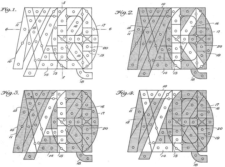
"This invention relates to improvements in illuminated signs and has for an object the provision of a single bank of lights which are arranged so that certain of the lights may be illuminated to form different numerals and letters of the alphabet, or other characters, the purpose being to arrange a number of banks together to spell out various words and sentences, which may be changed through the medium of switches and other operating mechanisms. "Another object is the provision of a device of the above character, in which th elights are arranged in channels with partitions dividing the channels and disposed so as to prevent the lights of an illuminated channel from showing in a channel not illuminate and thus add to the clearness and distinctness of the letter or character represented." (1:8ff) |
Faulkner's light grid is ingenious, but dependent on conventional letter shapes. While it provides a type "face" with a distinct style, those same features limit its application to other shapes. Faulkner does not specify what "other operating mechanisms" would be, but we can easily imagine a contact disk similar to that described by Raleigh above, able to select the required lights for a programmed sequence of letters. Yet there is a letterspace problem -- Even from only the three letters Figs. 2-3 shown in the patent, it can be seen that the origin point of each letter does not stand at a consistent 0,0 -- A stands to the left of K and to the right of Z. I do not see how several banks could be arranged to solve this problem.
|
|
|