telegraphic codes and message practice |
|||
margins : |
telautography |
||
|
|
|
ex John McGovern, The Fireside University for Home Circle Study and Entertainment, with complete indexes (Chicago, 1908 edition) |
Telautography must play a marginal role in this account of elementary signs : pictures because it does not involve analysis of an image (or even letterform) into basic elements for coded transmission and reconstitution. These distinctions should become clear by an examination of the patents described below. |
|
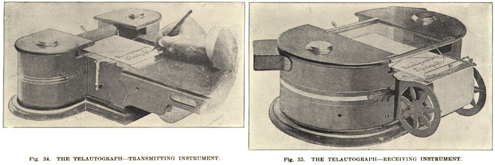
The telautograph is a system by which messages written in longhand at one station may be reproduced simultaneously at one or more other stations without material loss of any of the original characteristics... The transmitter consists of a stylus which is mechanically connected, through two sets of levers and appropriate swivel joints, to the contact arms of two variable rheostats in such a way that the horizontal and vertical components of the stylus movement are translated into corresponding current variations in two lines connecting the receiver. At the receiver the variations in the line currents produce similar movements in two coils or "buckets" within a magnetic field. The movements of these coils are communicated through a system of levers to a writing pen which reproduces the movements of the sending stylus. The pen is lifted from the paper and the paper is shifted to provide fresh writing surface by magnets which are controlled by superposed alternating current supplied by a buzzer located in the transmitter... The speed of operation is determined entirely by the rapidity with which the operator can write. |
|
Clokey, Allison A. "Telegraphy." in Pender, Harold and Knox McIlwain, eds. Electrical Engineers' Handbook : Electric Communication and Electronics (Wiley Handbook Series, 1936) : 11:01-35 (includes section on "telautograph system" as distinct from "facsimile transmission." Clokey's schematic illustration shows the essentials of the telautograph systems described by Foster Ritchie (1899 GB 24,048) and George S Tiffany (1910 US 954,150), all based on Elisha Gray's patents, some of which are presented below. Yet Clokey's account Yet as we shall see, several manifestations of the Gray system relied not on rheostats and current variations. Some of the patents incorporate a regular sequence — something like a "beat" — of polarized impulses that were less susceptible to induction and other line influences; moreover, the Gray system (and others) eventually would separate those signals from the power needed to actuate the mechanism, by means of relays. Each patent associated with Gray or with his companies represented some kind of improvement on its predecessors; the system did seem to stabilize in the 1920s, however. Telautograph (and much later Electrowriter) devices were used for intraoffice communications. The Dead Media and Office Museum websites listed below refer to their use in hospitals and clinics, insurance firms, hotels (front desk to housekeeping), banks, train dispatching, and even as a link between brokerages and cable offices. Telautography was used by the Air Force for dissemination of weather reports ("weather symbols not available on keyboards", writes Guitry). In 1899, then-head of the British Museum Reading Room, Richard Garnett, proposed the introduction of the Telautograph for paging books. Devices would be furnished at the catalogue desks, and patrons would retain a slip of their request. …How vast the improvement in the economy of the Reading Room! Garnett wrote, No more troops of boy attendants, with the inevitable noise and bustle; nothing but the invisible messenger speeding on his silent errand, and the quiet delivery of books at the desks: an un-paralleled scene of perfect physical repose in the midst of intense mental activity. Of course the improvement would not stop with the Reading Room, and ere long all departments would be connected by the writing telegraph. (Richard Garnett, Essays in Librarianship and Bibliography (London: George Allen, 1899) : 257; a transcription can also be found at here. other references Dead Media Project, working notes 05.5 (derived from Lewis Coe, The Telegraph: A History of Morse's Invention and its Predecessors in the United States (1993); notes that telautograph systems — specifically Foster Ritchie's 1900 design — were short-range instruments, not dependable over five miles. This shortcoming probably owed to their reliance on "current strength" over lines without repeaters; telegraph signals were more robust in this regard.) Dead Media Project, working notes 44.7 (discussion of later days of telautograph, 1960s-80s, when it went under the name Electrowriter) Elisha Gray (Marius Rensen, fax history) antique communications equipment (Early Office Museum, good on Gray Telautograph system) "The Telautograph." Manufacturer and Builder 25:4 (April 1893) : 76-77 (link to pageviews at Cornell University, Making of America)
|
|
US Patent No 461,472 (1891)
US Patent No 491,347 (1891)
US Patent No 494,562 (1893)
|
US Patent No 570,072 (1896)
UK Patent No. 24,048 (1900) US Patent No 954,150 (1922)
|
US Patent No 461,472
|
Art of and Apparatus for Telautographic Communication |
Elisha Gray (Highland Park Illinois) |
|
captions to come |
(enormous document, 10 sheets of drawings, 28 pages of specification and claims) In my present system these pulsations do not preferably directly operate the motors which move the receiving-pen as do the pulsations sent to line in the system of my prior patents. I now propose, preferably, to produce a constant strain upon the apparatus which drives the receiving-pen, this strain originating in a motor, revolving shaft, weight, or other device or force independent, as regards its source of power, of the transmitting instrument, and to govern the application of this force to the driving of the receiving-pen by means of an escapement operated by the pulsations above referred to. Thus each pulsation sent over the line will permit the receiving-pen to advance a space corresponding to one-half a tooth of the escapement-wheel, and as each pulstation represents a certain definite space traversed by the transmitting-pen and each tooth of the governing escapement-wheel of the receiver represents a certain definite space over which the receiving-pen is driven the movements of the transmitting-pen will be reproduced with almost absolute accuracy by the receiving-pen. (1:50ff)
|
US Patent No 491,347
|
Telautograph |
Elisha Gray (Highland Park Illinois) |
|
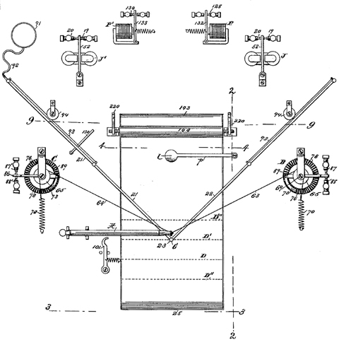
This passage regards the successive intervals and polarities of signals, that are used rather than a constant current, though varying in intensity : "The pulsations of successively opposite polarity sent to line from the transmitter cause a change of magnetic polarity in the pole pieces within the two coils of the magnet H', causing the armature 99 to be drawn first to one side and then to the other sustaining the restraint upon the receiving pen at regular successive intervals and permitting the escape wheel to revolve step by step, one step at each pulsation, in the direction in which the constant strain impels it. When a reversal occurs in the direction of motion of the transmitting pen the polarity of the current in the reversing circuit is changed, the armature of the magnet J' responds to this change, and the electrical condition of magnets X' Y' is reversed, so that the pen drum is given a tendency to reverse its direction of revolution and the direction of movement which it imparts to the pen carrying arm 21, and the motion in this reverse direction will continue until another reversal of polarity occurs in the reversing circuit…" (4:76ff) |
This would seem to be the "much simplified and improved" form of the invention described in The Manufacturer and Builder (April 1893) : The mechanism by which the movements of the pencil are duplicated is comparatively simple and positive in character, being controlled by a series of impulses sent over the line, constituting what is known among electricians as the "step-by-step" system of operation. We will endeavor to give a simple explanation of the devices employed. ¶ The pencil used at the transmitter has near its point a collar, with two small eyes in its rim. To each of these eyes is attached a fine silken cord, running off in two directions at right angles. Each of these cords passes around a small drum supported on a vertical shaft. Beneath the drum, and attached to the same shaft, is a toothed wheel, so arranged that when either section of the cord winds upon or off of its drum, a number of teeth will pass a given point corresponding to the length of cord so wound or unwound. Thus, if the pencil in its movement winds up one inch of one of the cords, forty of the teeth of the wheel will pass by a given point. Each one of these teeth stands for a single electrical impulse sent over the line, as will later be seen. ¶ The mechanism of the receiving instrument is practically the duplicate of that of the transmitter, but, as previously noted, its motions are purely automatic, being controlled by the electric impulses sent over the line from the transmitter. The receiver is provided with two escapements, which are actuated by polarized relays, and so constructed that each electrical impulse received from the line permits the escapement wheel to feed one step either forward or backward. These escapement wheels are mounted on vertical shafts, which carry drums of the same size as those of the transmitter. The forward or backward movements of the escapement wheels, therefore, are imparted to the drums. To these drums are attached, by means of cords, pen arms of aluminum, which are hinged together at the point where the pen is carried. The writing is done with the point of a small capillary glass tube, to which the ink is fed through one of the aluminum tubes, which is kept supplied from a small reservoir. The point of the glass tube rests upon tbe paper, and when moved over it by the motion of the hinged arms to which it is attached, the ink is caused to flow from it; when it is raised from the paper the ink is retained in the tube by capillarity. ¶ It is not difficult now to understand how the duplication of the writing at the receiving end of the line is effected. When a movement in one direction of one of the toothed wheels of the transmitter is made by the writer, a certain number of electric impulses, according to the length of the line, is sent over the line, and the escapement wheel at the receiver will be given a movement forward or backward, as the case may be, the same distance, carrying the drum around in the direction corresponding to that given by the writer's pencil to the drum at the transmitter. |
US Patent No 494,562
|
Telautograph |
Elisha Gray (Highland Park Illinois) |
One finds two means of generating signals from the transmission to the receiving station: one is a sequence of polarized signals, that keep the system moving along its current trajectory until an additional signal — of one polarity or the other — starts it on a different trajectory. The second system uses rheostats that vary the strength of a constant current. The second system is described in this patent. A writing pen attached by pantograph to rheostats that generate current variations that, in a receiving station, actuate magnets that control via a similar pantograph arrangement a writing implement. The system is suited to handwriting and other forms of line art, but not to photographs or the transmission of tonal values beyond black-and-white line art. The patent specification starts by describing the shortcomings of previous systems of its class. Those failings include these :
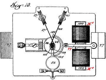
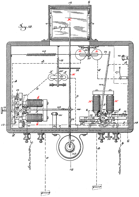
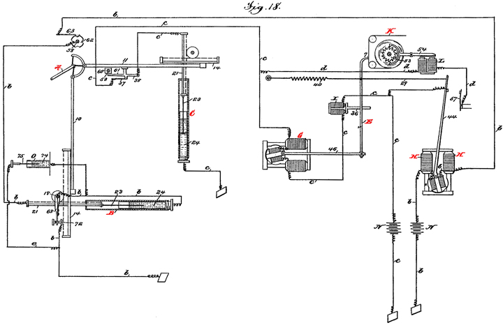
Figure 10 below shows the receiving instrument in plan; my selective annotations to the right. See Figure 18 further below which, while intended to illustrate the electrical connections, usefully shows the entire system, including transmitting instrument on the left, and the receiving instrument on the right. |
|
Key components of the receiving instrument, shown in plan in Fig 10 immediately to the left, and in Fig. 18, below right, are : Receiving pen E, which is a fountain pen "composed of a glass tube of very fine bore, arranged in a substantially horizontal position with its end bent downward to form a writing point 7", which can be seen to deposit ink by siphon action to paper ribbon K. The rear end of the pen E is pivoted to the end of a lever leading to magnet G, and connected by cord or light rod to second magnet H. The force of magnets G and H is controlled by the resistances B and C to which they are connected. Magnet G imparts movement to the pen corresponding to the down and upstroke movements of the transmitting pen; magnet H controls the pen movements in direction of the length of the line. Electromagnet L controls, via escapement and armature 55, the roll upon which the paper Kis wound. |
Key components of the transmitting instrument shown in Fig. 18, below left, are : Transmitting pen A, connected by two rods which run to resistances B and C. Resistance B carries current as the pen is moved from left and right across the writing sheet, while resistance C varies current as the pen is moved to make down and up strokes in forming characters. |
|
…a brief outline of the system will be first given. The system consists primarily of two instruments; a transmitting instrument and a receiving instrument. The transmitting instrument consists primarily of a transmitting pen which can be moved by the operator over a field of considerable extent. If the instrument is designed for transmitting messages in writing the field will be equal in one direction to the length of a line of the writing and in the other direction to the distance above and below the line occuped by any character. The transmitting pen is arranged to control resistances located in two electric circuits and arranged to increase and diminish the strengths of the currents passing over their resepective circuits, as the pen is moved along the length of the line and above and below the line. These two circuits pass through the receiving instrument and are connected to two electromagnets the armatures of which control two levers in such manner that the levers are caused to vibrate a greater or less distance according to the strengths of the currents passing through the magnets. By this means the movements of the transmitting pen along the line and above and below the line will, through the variations caused in the currents passing over the circuits, impart corresponding movements to the two levers in the receiving instrument. The movements thus imparted to the two levers in the receiving instrument are, through suitable connections, transmitted to other parts of the instrument, preferably directly to the receiving pen, in such a way as to exactly reproduce the movements of the transmitting pen and thus reproduce an exact fac simile of the line of writing or other matter written or traced by the operator. ¶ Cooperating with the receiving instrument, or forming a part thereof, is a means for supporting a sheet of paper or other recording surface, either in the form of a continuous band or strip or in the form of a pad or a detached sheet, in proper position beneath the pen to receive the message and a means for shifting this paper after the completion of each line of writing, so as to bring it in proper position beneath the pen to receive the succeeding line. (2:23ff)
|
US Patent No 570,072
|
Telautograph |
George S Tiffany (Highland Park Illinois), assignor to the Gray National Telautograph Co |
|
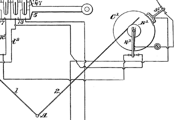
Fig. 1 detail at left, showing transmitting pen A, pen arms 1 (partial) and 2, and "interruptor" disk C'. This system addresses shortcomings of its predecessors : "It is difficult in systems of this kind, where pulsations of opposite polarity are employed, to introduce variations in the strength of impulses sent from the transmitter for the purpose of performing a series of operations over the same line-wires, owing to the inductive effects of those currents upon the magnets which they operate... " The solution lay in use of "pulsations of successively opposite polarity in the magnets controlling the escapement, these pulsations corresponding in number with the extent of movement of the transmitting pen." The patent reserves the line current for the signals (pulsations) themselves; deteriorating line current (especially over long lines) was such that a separate escapement-magnet and a relay is employed. (2:53ff)
|
|
The main feature of this patent may be the dedication of line current to signal (pulsations), and use of escapement-magnet and relay for mechanical operation.
|
UK Patent No 24,048
|
Improvements in Telautograph Apparatus |
Foster Ritchie (Electrical Engineer, Hampstead, Middlesex) |
|
"In these apparatus the pen or tracer which writes or draws at the sending station is in the joint which connects two rods extending from pivotted lever arms, these rods being at angles to each other, and the pen at the receiving station is likewise in the joint connecting a pair of similar rods jointed to lever arms. By means of electrical currents transmitted by the movements of the sending arms, the receiving arms are caused to make similar movements, and thus the pen of the receiving rods makes a copy of the writing or drawing made by the tracer of the sending rods. The movement of each receiving arm in conformity with that of the sending arm has been determined in several ways. One way proposed several years ago was by making the sending arm or a brush connected with it travel over a series of contacts by which a less or greater resistance was introduced into the circuit connecting the stations, the receiving arm being thus caused to move over a greater or less course. The present invention relates to telautographic apparatus operating on this principle..." (1:5ff) |
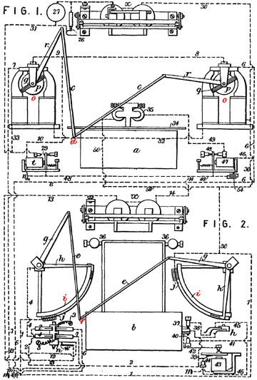
Fig. 1 is receiving instrument, Fig. 2 is sending instrument. In receiving intrument Fig. 1, o are magnets, controlling coil q which in turn controls the receiving arms r and c, and pen d. In sending intrument Fig. 2, tracer f actuates sending arms which interact with rheostats i, varying current that will actuate the magnets, controlling coil and pen in the receiving instrument. |
The arm mechanisms are a kind of pantograph with control, respectively, over movements in vertical and horizontal directions; their combination of course yields movements in all other directions. Ritchie had been an assistant to Elisha Gray; this patent represents an improvement on Gray. G S Tiffany's US patents are elaborations of these basic principles. Because the system depended on varying current strengths, rather than coded (telegraphic) signals, it was not suited at least initially to long distances (see Coe).
|
US Patent No 954,150
|
Telautograph |
George S Tiffany (Summit, New Jersey), assignor to the Gray National Telautograph Company |
|
|
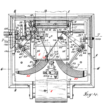
Fig. 4 — sending instrument Transmitting tracer 12 (figure added by me to this drawing) is shown above writing platten 11. The tracer, by means of pivotally connected rods 46 and 47, and other arms 48 and 49, moves journaled roller contacts back and forth along a pair or rheostats 57 and 58 that generate currents of varying strength to operate the magnets in the receiving instrument. A record of the message is made at the sending instrument on record strip 5. |
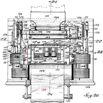
Fig. 20 — receiving instrument Only two details are highlighted in red here : receiving pen 137, and paper strip 150. The pen is controlled by magnets and rods that are familiar from the patents shown above.
|
The main outlines of the Gray and especially Ritchie patents are clearly evident in the plan views above. I have not examined this specification closely enough, nor compared it with Tiffany's earlier patents 668,889, 668,890 and 668,895 (all granted February 26, 1901) to determine the exact nature of its "improvements". Tiffany's 1924 US 1,494,083 involves an automatic exchange for telautograph systems.
|
|
|
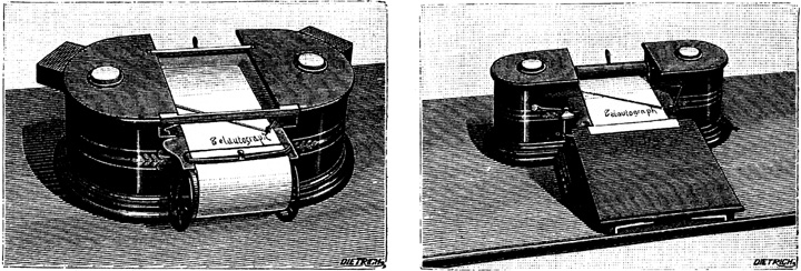
receiver |
sender
|